65 Results
View results:
Sort by:
![Spans Based on Figure 5.2 from [1]](/en/webimage/039540/3493372/01_Abmessungen_EN.png?mw=640&hash=a3c436931baff3514db261b2d11bfa39abae9170)
In order to correctly design a downstand beam or a T-beam in RFEM 6 using the Concrete Design add-on, it is essential to determine the flange widths for the rib members. This article describes the input options for a two-span beam and the calculation of the flange dimensions according to EN 1992-1-1.

This example shows you how to quickly determine the buoyancy or the uplift limit state of a vessel in RFEM.

Foundations including dimensions can be saved as a template in a user-defined database.

In RFEM 5 as well as RSTAB 8 in RF-/FOUNDATION Pro, you can save the foundation dimensions for all five foundation types as foundation templates in a user-defined database and use them later in other models.

In RF-/FOUNDATION Pro, the foundation design requires the definition of the corresponding loading (load cases, load combinations, or result combinations) for different design situations (STR, GEO, UPL, or EQU).

In RF‑/FOUNDATION Pro, reinforcement drawings are displayed after designing the foundation, where you can record all necessary structures of the reinforcement steel.

When modeling structural bearing systems, especially hall structures, some substructures of a foundation with no influence on the rising structure are not modeled in RFEM/RSTAB. In the case of hall structures, these are, for example, reinforced concrete floor slabs, strip foundations, and the ties between column foundations.
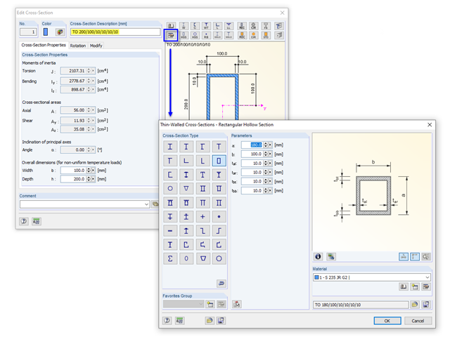
If you define a parametric cross-section in the library using its dimensions, the geometric properties are coded in the cross-section description; for example, "TO 200/100/10/10/10/10".

An elastic foundation can be applied to a member. Thus, the influence of the soil is usually included in the modeling. Member elastic foundations can only be defined for the "Beam" member type.

In RF‑/FOUNDATION Pro, the available reinforcing steel diameters can be adjusted by the user. The adjustment of the available rebar diameters works similarly to the same function in the RF‑/CONCRETE (Members) and RF‑/CONCRETE Columns add‑on modules.

In RF-/FOUNDATION Pro, the user can freely select the proportion of the relieving soil pressure by means of the factor kred.

In RF‑/FOUNDATION Pro, you now have the option to design a foundation at one or several nodes of the model.

The RF-/LIMITS add-on module allows you to compare the ultimate limit state of members, member ends, nodes, nodal supports, and surfaces (RFEM only) by means of a defined ultimate load capacity. Furthermore, you can check nodal displacements and cross-section dimensions. In this example, the column bases of a carport are to be compared with the maximum allowable forces specified by the manufacturer.

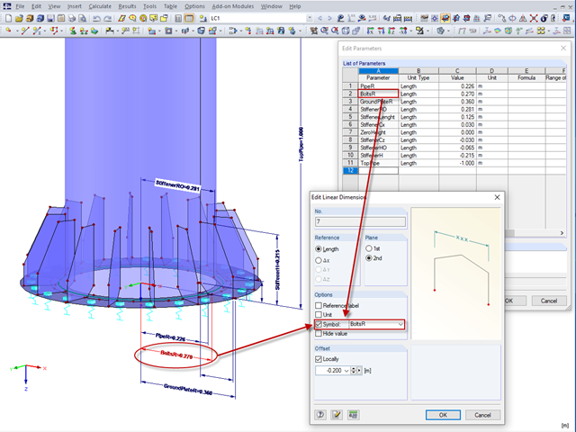
In RFEM and RSTAB, different graphical representations of the foundation dimensions are available.

For foundation design, it is necessary to define the relevant loads for the respective design situations (STR, GEO, UPL, EQU).

When calculating foundations according to EC 7 or EC 2, different foundation types or sizes are usually used in one object. However, boundary conditions like the soil parameters, the materials for foundations, concrete covers, and the load combinations selected for design remain the same for all foundations, as a rule.

You can use the elastic support option to avoid singularities due to a fixed nodal support in RFEM. This can be defined directly in the dialog box of the nodal support as a column in Z. It is necessary to take into account the geometry of the column, the material, and the support conditions. Here, we want to look at the option of modeling the column as a surface foundation.

Often in RFEM, only part of a surface must be loaded, not an entire surface. A typical case of this is soil pressure. For this purpose, there is the option of defining free surface loads. They are surface-independent and are displayed in defined coordinate dimensions in the graphic.
In RFEM 5 and RSTAB 8, it is useful to parameterize frequently occurring components with variable dimensions. In the Block Manager, you then can specify new dimensions and import them in a new or existing file.

In RF-/FOUNDATION Pro, a graphical display of the result details is available. To see them, go to Window 2.2 Governing Design Criteria after the calculation. In the interactive graphic of this window, individual design-relevant values can be displayed for each design performed.

If nonlinear effects - such as failing supports, foundations, member nonlinearities, or contact solids - are used in the model, you can deactivate them in the global calculation parameters.

The same structures are often needed in several projects, such as the purlin with columns and braces in this example. The dimensions can be changed directly in RFEM or RSTAB by shifting the nodes.

In RF‑/FOUNDATION Pro, the reinforcement to be placed in the foundation slab and, if necessary, the bucket links, is displayed in a 3D rendering and in the reinforcement drawings.

In the RF-/FOUNDATION Pro add-on module, you can select the automatic dimensioning of the foundation plate geometry. In the dialog box for the design parameters of the foundation plate, you can, for example, specify the increment for the increase of the base area and the foundation plate thickness. You can also automatically increase the covering for a stabilizing effect of the geotechnical designs.
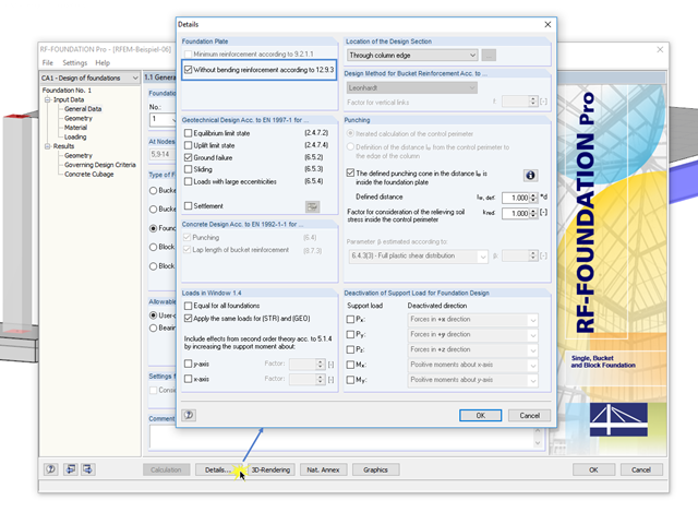
In RF-/FOUNDATION Pro, you can also calculate unreinforced foundation plates according to Section 12.9.3 of EN 1992-1-1 [1]. To do this, select the "Without bending reinforcement according to 12.9.3" check box in the "Foundation Plate" section of the "Details" dialog box.
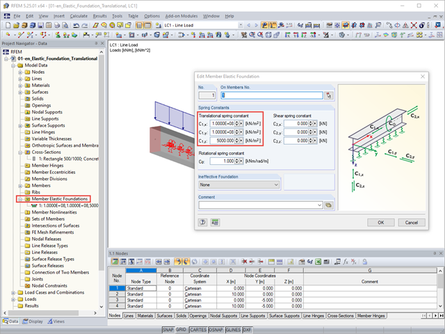
An elastic foundation can be applied to a member. The foundation is used to include the influence of soil in the modeling. Member elastic foundations can only be defined for the "Beam" member type.

In RF-/FOUNDATION Pro, you can also consider the concrete cover for the foundation according to EN 1992-1-1.
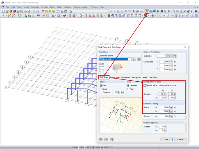
The length of the guidelines corresponds to the dimensions of the set grid and can be adapted by setting the grid.
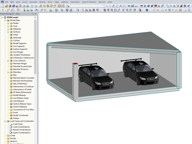
In RFEM 5 and RSTAB 8, you can add visual objects to the model in order to make a convincing impression on your client when presenting the structural model. These objects allow both laypersons and engineers to better understand the dimensions of the system.

In RFEM 5 and RSTAB 8, you can design foundations according to EN 1992‑1‑1 and EN 1997‑1 in the RF‑/FOUNDATION Pro add‑on module.